
In harsh-environment interconnect systems, a circular connector is only as robust as its backshell. While often viewed simply as a rear accessory, the backshell provides the essential interface between the rigid connector shell and the flexible cable bundle. Selecting the wrong configuration compromises the mechanical integrity, environmental sealing, and electrical continuity of the entire wiring harness.
At its core, a backshell must fulfil three strict engineering requirements:
A typical high-performance cable assembly as shown in figures 1 and 2 utilises a multi-layered mechanical structure. The backshell mates directly to the rear accessory threads of the connector. Moving up the cable, a band termination strap, ensures electrical continuity of the cable braid to the backshell and connector assembly before the final heat shrink boot mechanically holds the cable in place and provides environmental protection.
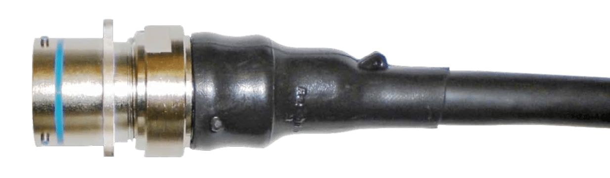
Figure 1: Finished connector assembly, with backshell fitted and heat shrink protection
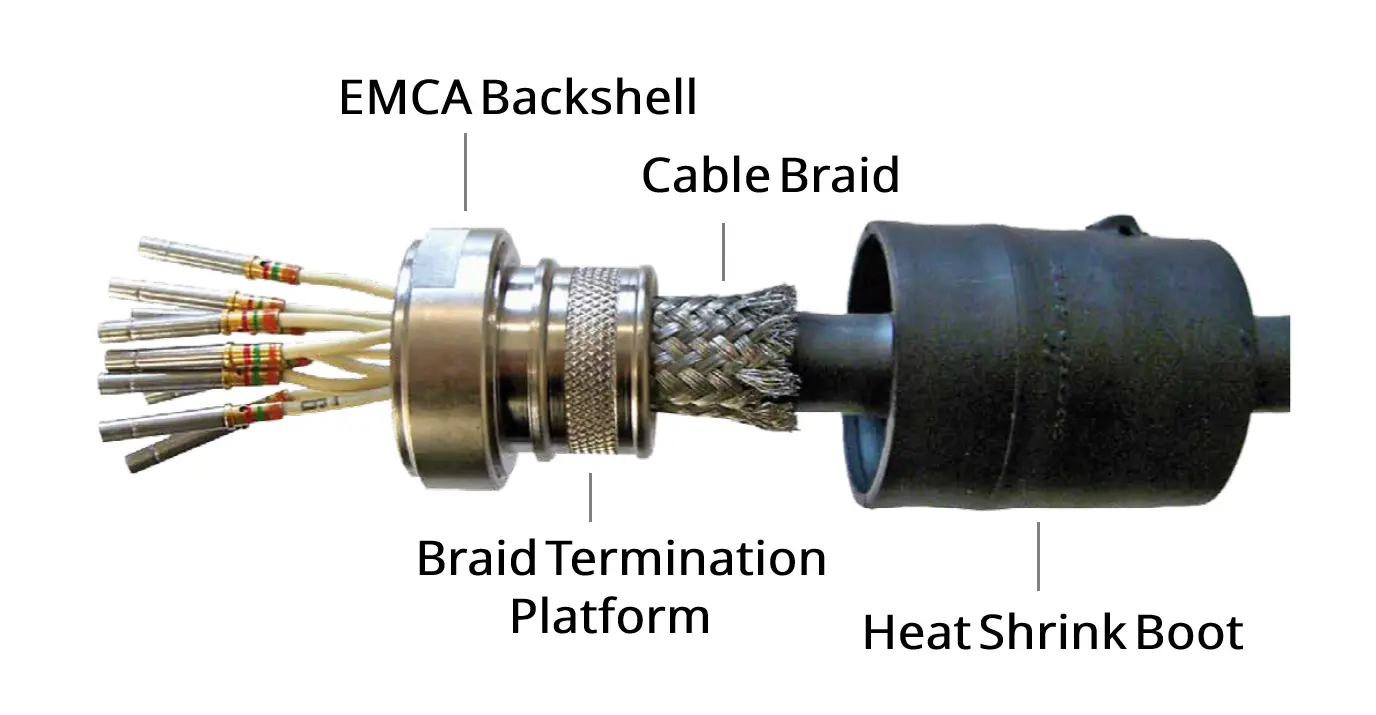
Figure 2: Prior to termination of cable braid to backshell platform and fitting of heat shrink boot.
Most aerospace, defence, and heavy industrial applications revolve around a small number of military connector specifications. When selecting a backshell, the key requirement is compatibility with the connector family, including the correct shell size, entry size and accessory thread.
Key accommodation differences
Procurement warning: Always verify the correct connector modification code (Mod Code) when matching parts. Rear accessory threads vary dramatically between Series I, II, and III variants within the same overarching MIL spec.
When specifying a backshell for a new wiring harness layout, design engineers must systematically address four primary physical variables:
Selecting the correct material and plating finish is just as critical as the mechanical design itself. The right plating ensures long-term corrosion resistance, reliable conductivity for EMI/RFI shielding, and environmental sealing against moisture and salt fog. Historically, Cadmium Olive Drab was the military standard due to its excellent track record and conductivity, but its toxicity and strict RoHS regulations are driving the industry toward safer alternatives. Today, options range from cost-effective Electroless Nickel for general aerospace applications to advanced RoHS-compliant, cadmium-free Hybrid Finishes that offer 500 hours of salt spray resistance while preventing galvanic corrosion between mismatched connector shells.
For a complete breakdown of available finishes—including Zinc-Nickel, Stainless Steel, Marine Bronze, and proprietary Hybrid options—read the full Material Plating Overview to determine the best balance of compliance, cost, and performance for your application.
Physical space constraints inside electronics chassis, vehicle bulkheads, or aircraft wings govern your cable routing geometry. Backshells are engineered in three universal profiles:
The 90-degree configurations shown demonstrate how right-angle units solve routing constraints in tight quadrants while integrating a knurled platform specialized for robust shield grounding.
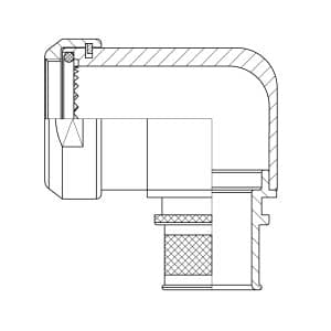
Figure 4: EMCA 90° Band / CFS Backshell - A37-525
The entry size defines the maximum cable diameter that can pass through the rear of the backshell before any sealing gland, strain relief, or heat-shrink boot is fitted. Selecting the correct entry size is essential for achieving reliable strain relief, environmental sealing, and long-term cable protection.
When choosing an entry size, engineers should start with the finished outside diameter of the cable assembly—not the conductor size or individual core dimensions. Any outer jacket, braid, shielding, sleeving, or protective wrap that will pass through the backshell must be included in the measurement. If a heat-shrink boot or cable gland is to be installed, ensure the backshell entry is compatible with the required accessory.
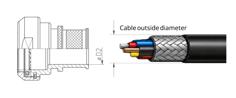
Figure 5: Select the smallest backshell entry size that comfortably accommodates the finished outside cable diameter
An entry that is too small may prevent assembly or damage the cable during installation. An entry that is too large can compromise strain relief and make it difficult to achieve an effective environmental seal, particularly in harsh operating environments.
As a general rule, select the smallest entry size that comfortably accommodates the finished cable diameter while allowing sufficient clearance for assembly. EMCA manufacturer dimensional tables should always be consulted, as entry size designations vary between backshell series and standards.
The choice of shielding / cable interface directly impacts your production assembly speed and high-frequency EMI protection:
Banding adapters : Employs a tensioned stainless steel strap or memory ring to clamp the overall braided shield onto a dedicated rear platform. This produces low DC resistance and exceptional high-frequency attenuation.
Cone & ring termination: Compresses the braided shield between matching internal male and female tapered metal cones. Highly reliable and field-repairable without proprietary banding tools.
Strain relief clamps (Saddle clamps): Uses simple mechanical bars to compress the outer cable jacket. Best for non-shielded heavy power cables where physical strain relief outweighs EMI shielding.
This is key area, for more detailed information read our guide to cable shielding and EMI/RFI termination in backshells for more information.
Designing complex wire harnesses requires access to components that offer absolute mechanical interchangeability without commercial lead-time bottlenecks.
Explore our fully qualified inventory lines or map your legacy component profiles directly through our engineering tools:


