
Electromagnetic Interference (EMI) and Radio Frequency Interference (RFI) are silent killers of signal integrity in modern aerospace, defence, and high-speed industrial networks. High-frequency digital signals, radar emissions, and nearby heavy power systems can easily introduce cross-talk or induce unwanted currents in unshielded conductors.
To isolate these signals, high-performance cable assemblies use conductive metallic braids. However, a shielding system is only as effective as its termination point. The backshell serves as the mechanical and electrical bridge that completes the 360-degree Faraday cage between the cable braid and the connector shell.
Historically, technicians would gather the braided shield at the end of the cable, twist it into a single wire (known as a "pigtail" or drain wire), and screw it to the backshell. While this technically grounds the shield, the pigtail itself acts as a "standing antenna". At higher frequencies, this small loop of unshielded wire actively radiates or receives EMI, defeating the purpose of the shielding entirely.
Modern interconnect systems avoid creating a standing antenna by ensuring an even 360-degree clamping force of the braid to the backshell body. Choosing the best approach is still a critical decision as selecting the wrong termination methodology can lead to signal attenuation, costly manufacturing bottlenecks, or catastrophic field failures. This comprehensive guide analyzes the five leading shield termination mechanisms used in MIL-spec backshells: Precision Tie-Bands, Constant Force Springs, Memory Rings, Single Cones, and Double Cones.
To prevent RF energy from leaking or entering the system, the shield termination must exhibit low DC resistance and absolute circumferential coverage. Any gap or high-resistance junction becomes an antenna.
The assembly relies on a sequential layering of elements. The exposed cable shield braid passes over the rear platform of the backshell adapter before a sealing layer, such as a heat shrink boot, isolates the completed termination from environmental factors.
Platform-based backshells feature a machined, knurled, or smooth rear entry platform where the cable braid is drawn over the rear of the backshell body and compressed externally. Many high-performance backshell lines are engineered to accept any of these methods, leaving the choice down to your assembly and environment requirements. EMCA offers backshells with a platform that supports all of these. Look for "Band / CFS Backshell" across our ranges.
A tie-band is a flat, pre-coiled strip of high-tensile 300-series stainless steel. It is looped around the braid over the backshell platform, pulled to a precise tension, locked, and sheared.
The mechanism: Relies entirely on a specialized manual or pneumatic banding tool. The tool pulls the band to a digitally calibrated mechanical tension, crimps a locking buckle, and cuts the excess strap perfectly flush.
The profile: Rigid and permanent. Once tensioned, the band does not move or stretch. It provides the highest possible mechanical pull-out resistance, locking the braid down indefinitely.
Best used for: Factory-assembled wiring harnesses destined for high-stress aerospace, missile, or military vehicle applications where the assembly is permanent and space envelopes are ultra-tight.
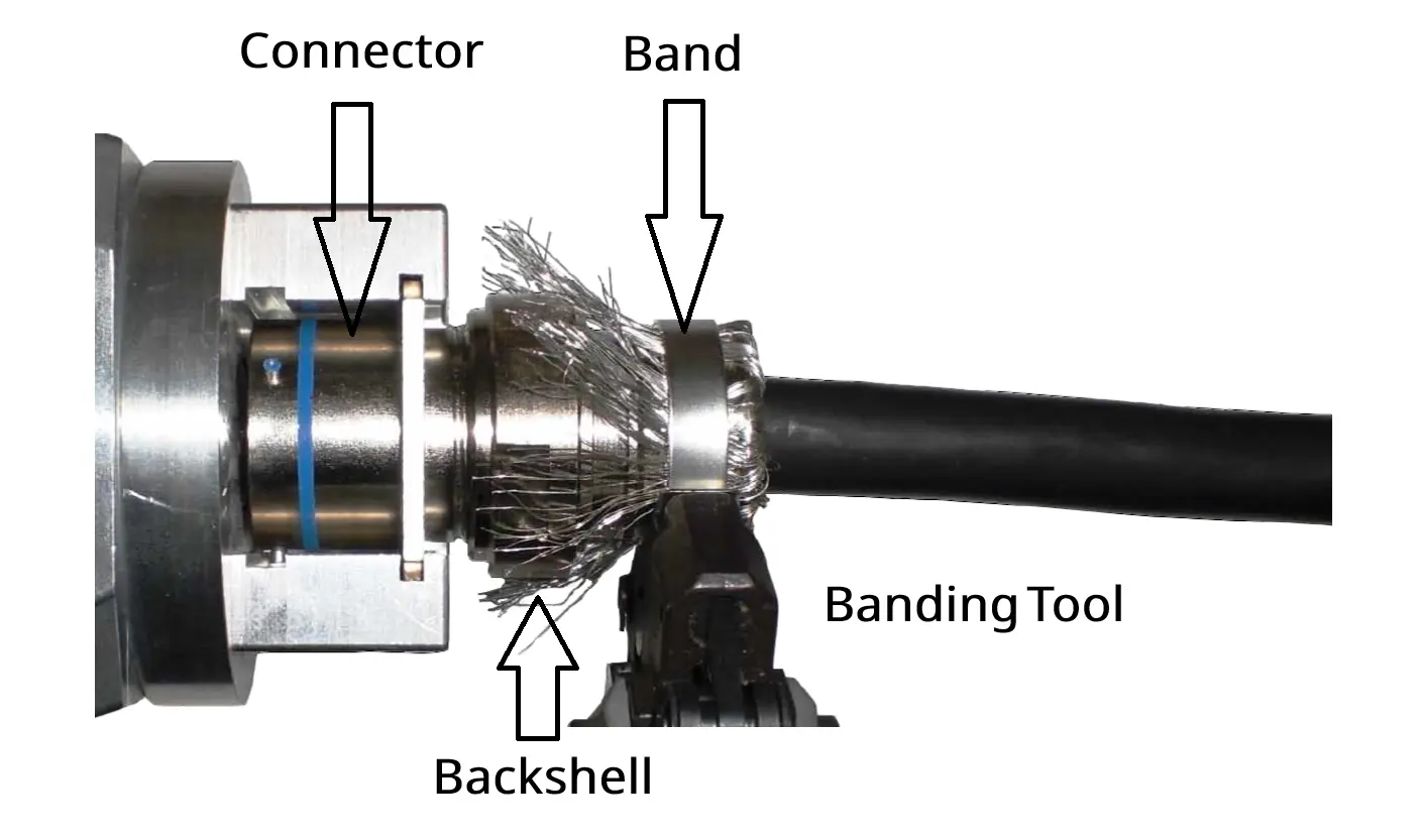
Figure 1: Shield Termination - Banding Strap. Cable braid pulled over the rear platform of the backshell and secured using a stainless steel band.
A constant force spring is a roll of fatigue-resistant spring steel that has been tightly coiled during manufacturing to give it a strong "elastic memory."
The mechanism: 100% Tool-Free. The operator manually unrolls the spring strip, wraps it tightly around the cable braid over the backshell platform (typically 2 to 3 full wraps), and lets it snap into place. The spring constantly tries to return to its original wound diameter, exerting continuous radial force. The assembly is typically finished with adhesive-lined heat shrink or self-amalgamating tape.
The profile: Dynamic and elastic. Because it is a spring, it applies uniform pressure that flexes. If severe environmental temperature swings cause the cable materials to expand or contract, the spring dynamically adjusts, maintaining an uninterrupted grounding path.
Best used for: Rapid field repairs, tactical communications equipment, or systems prone to extreme thermal cycling where rigid bands might cause underlying insulation materials to cold-flow over time.
Manufactured using advanced shape-memory alloy technology, the EMCA Memory Ring contracts uniformly when heat is applied. This controlled radial contraction generates an evenly distributed clamping force around the cable braid, ensuring secure mechanical retention and a low-resistance electrical interface to the backshell.
The profile: Lightweight and compact design – Provides a high-performance solution without adding bulk to the connector system.
Best used for: Unlike other methods, the EMCA Memory Ring delivers a controlled and repeatable termination process. This reduces assembly variability while improving consistency across cable harness production.
For applications where external bands or springs are undesirable, the cone-and-ring (or cone-clamp) methodology is an engineering favorite. Instead of using external compression on a rear platform, these systems utilize threaded, precision-machined internal components to radially lock the shielding into place. They are completely tool-free (requiring only standard wrenches) and 100% reworkable.
The single cone configuration is the standard workhorse for individual or overall single-braid shield layouts.
The mechanism: The backshell housing contains an internal male taper (the cone core). The technician combs out the cable’s shield braid, flips it smoothly over this taper, and threads a female cone-shaped clamping nut down over the assembly. This squeezes the braid evenly in a perfect 360-degree circle against the core.
Best used for: Standard defence, rail, and industrial applications where you are terminating a single overall shielded layer and require high field serviceability without specialized inventory.
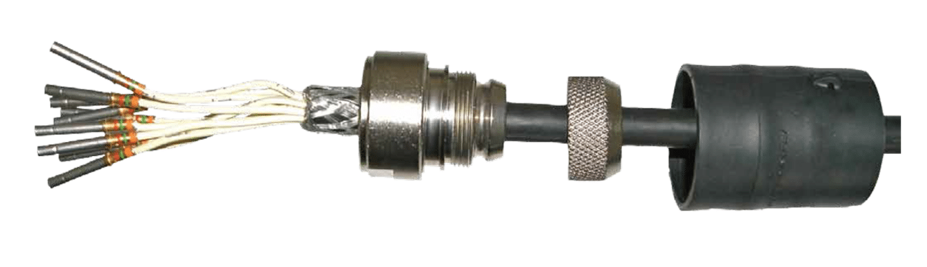
Figure 2: Single cone backshell and heatshrink boot prior to attaching connector and terminating cable braid
When dealing with extreme-environment aerospace or defense hardware (often conforming to stringent specifications like VG 95319-1011 or HE308), you will frequently encounter dual-shielded cables—meaning an inner core shield wrapped inside a separate, outer overall shield braid. Trying to crush both thick, overlapping braids into a single cone system creates a bulk mismatch, leading to micro-gaps and high-frequency EMI leaks.
The mechanism: A double cone backshell incorporates two separate, nested internal cones. The inner shield braid is pulled over and clamped by the primary cone system, while the outer overall shield braid is drawn over and clamped by a secondary nested cone system.
Best used for: High-attenuation, heavy-vibration environments where both the primary and secondary screens must maintain distinct, perfect electrical continuity back to the connector shell without compromising mechanical grip.
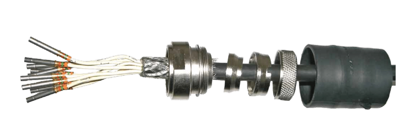
Figure 3: Double cone backshell prior to attaching connector and terminating cable braid
| Engineering Variable | Precision Tie-Band | Constant Force Spring (CFS) | Memory Ring | Single Cone | Double Cone |
|---|---|---|---|---|---|
| Tooling Required | High (Calibrated Banding Gun) | None (Hand-installed) | Heat Source (Heat Gun) | None (Standard Wrenches) | None (Standard Wrenches) |
| Reworkability | Destructive Only (Must be cut/replaced) | 100% Reusable (Unroll & re-apply) | Destructive Only (Must be cut/replaced) | 100% Reusable (Unscrew & adjust) | 100% Reusable (Unscrew layers independently) |
| Mechanical Grip | Superior | Moderate | Secure / Excellent | Excellent | Exceptional |
| Thermal Cycling Response | Static | Dynamic (Self-adjusting) | Dynamic (Shape-Memory) | Static | Static |
| Dual-Shield Capability | Moderate (Requires step platform) | Moderate (Requires step platform) | Moderate (Requires step platform) | Poor (Risk of micro-gaps) | Superior (Designed for dual-screens) |
| Assembly Profile | Ultra-Low / Compact | Medium (Layered wraps) | Ultra-Low / Compact | Medium | Large (Dual internal chambers) |
Galvanic compatibility: Ensure that the plating material of your backshell matches the material of the cable braid. For instance, pairing a cadmium-plated backshell with a silver-plated copper braid creates a severe galvanic cell, accelerating corrosion in humid environments.
Thread protection in cone systems: When prepping single or double cone styles, ensure the braid is trimmed perfectly flush with the shoulder of the cone. Stray, loose strands caught in the internal threads won't just ruin your grounding path—they can gall the precision-machined aluminum-alloy threads, permanently locking the backshell half-open.
Braid trimming precision: Loose strands from an incorrectly trimmed or uncombed braid can migrate into the connector cavity, causing catastrophic short circuits between high-density pin layouts.
Optimizing an interconnect system for signal integrity requires components with precise shell tolerances and high-quality plating configurations.
Explore our qualified product categories to match your electrical shielding layout:
Secure your shielding paths with our heavy-duty MIL-DTL-38999 Series III backshells
Examine lightweight options in our MIL-DTL-26482 Series II range of backshells
Locate direct drop-in alternatives for existing part configurations using our Equivalent Part Finder

